How PacFully represents foldable packaging as parametric SVG: panels, cut vs crease, dimension sync, artwork clip paths, and vector export — with honest limits.
Dielines exist for 6 box templates only (mailer, tuck-end, RSC, drawer, pillow, gable). Bottles, jars, cans, pouches, and tubes correctly set dielineAvailable: false.
1. What a dieline is here
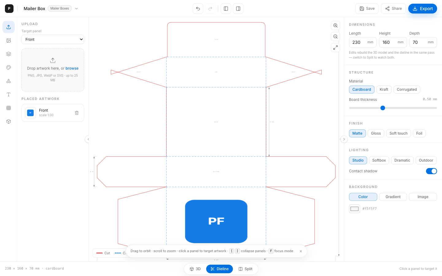
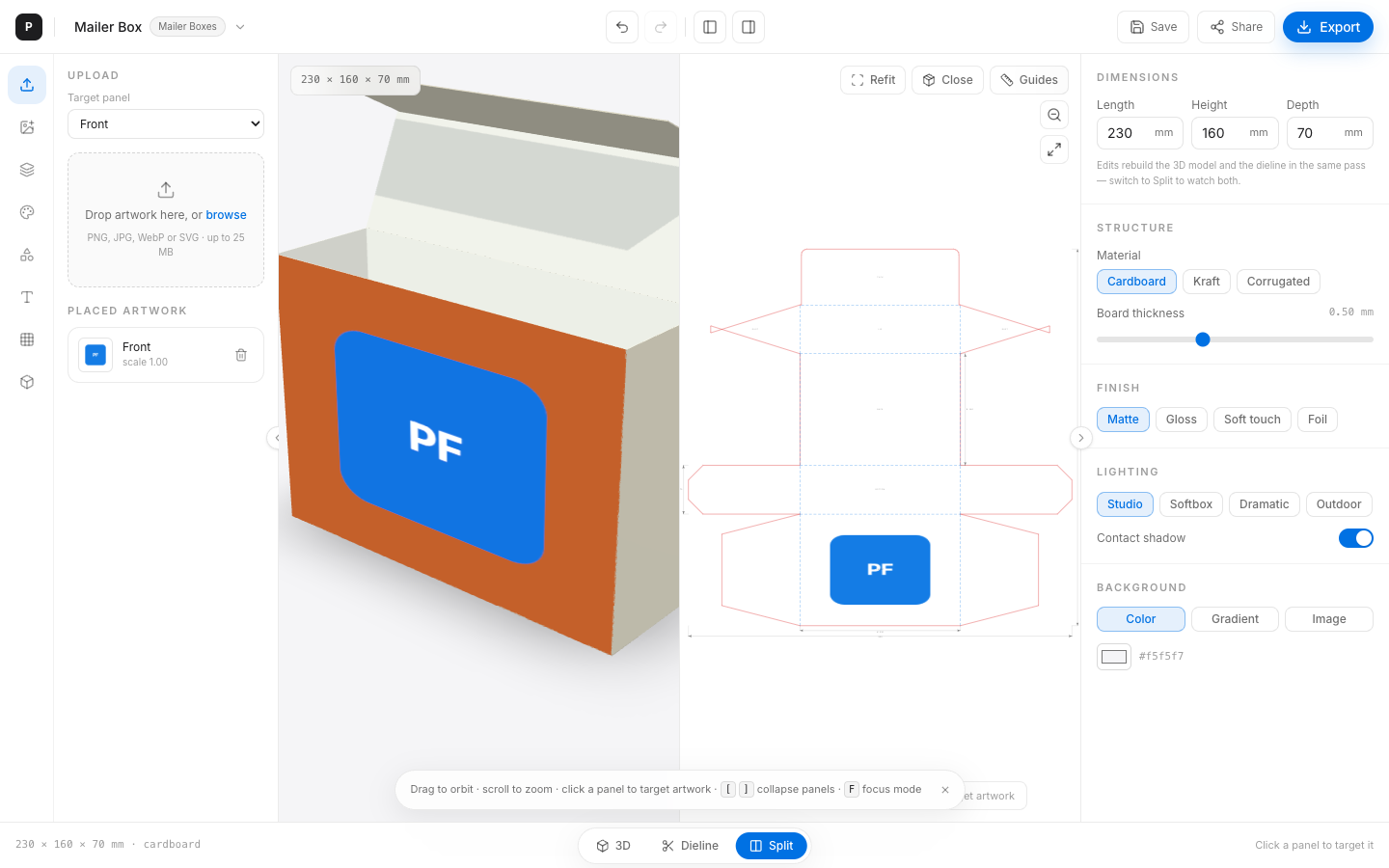
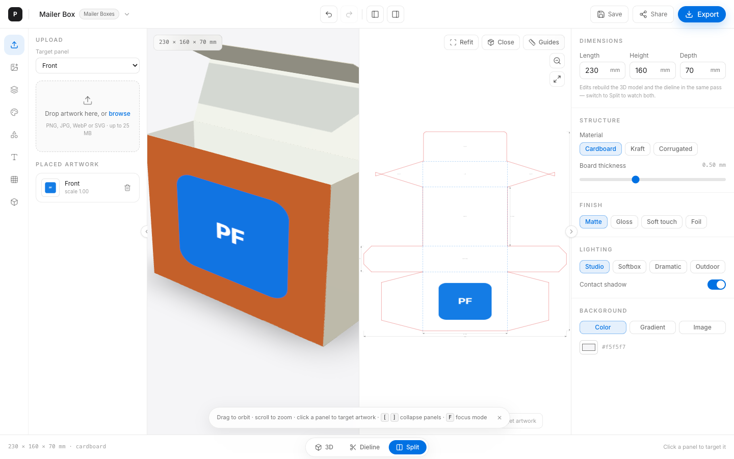
In PacFully a dieline is a parametric SVG document generated from the same millimetre dimensions as the 3D mesh:
- Cut — solid red perimeter (through-cut)
- Crease — dashed blue fold lines
- Bleed — offset guide (~3 mm
DIELINE_BLEED_MM) - Panel regions — labeled areas mapped to 3D panel ids
- Dimension annotations — live mm callouts
DXF export mirrors layers: CUT, CREASE, BLEED, DIMS (R12, mm units).
2. Opening dieline view
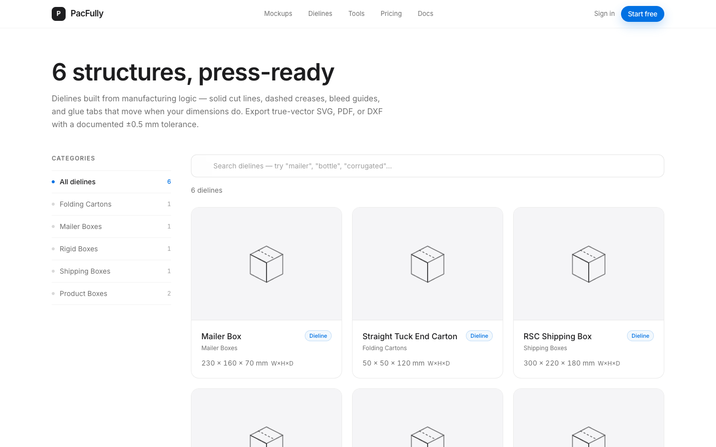
- Gallery: /dielines lists foldable structures, then opens the editor.
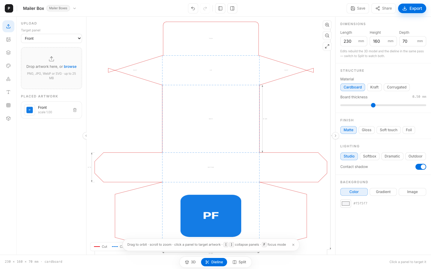
- Editor: bottom toggle → Dieline (or Split).
3. Reading the sheet
- Legend: Cut (red bar) · Crease (blue dashed) · “mm · click a panel to target artwork”.
- Zoom controls (top-right): zoom in/out, fit to sheet.
- Click a panel region to select it — mirrors 3D selection for artwork targeting.
4. Editing dimensions → live update
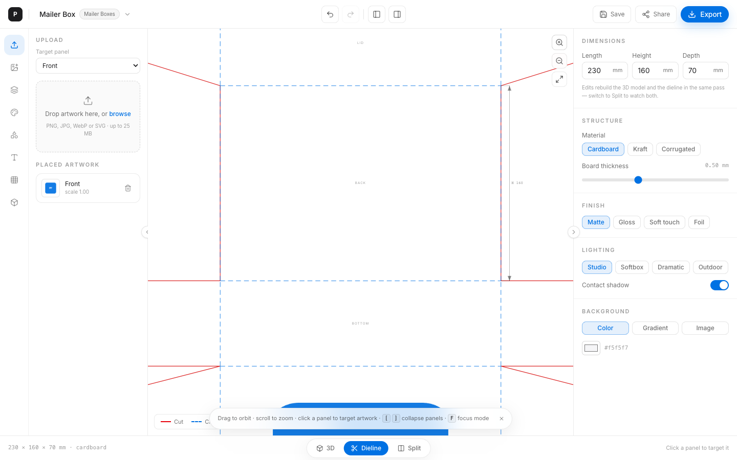
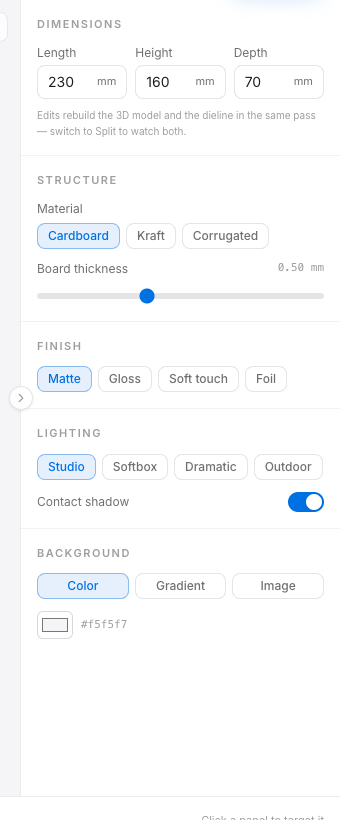
With the dieline (or split) visible, change Width / Height / Depth on the properties panel. generateDieline(templateId, dims, thickness) re-runs in the same React commit as the 3D rebuild. There is no separate “update dieline” button.
5. Artwork overlay on dieline panels
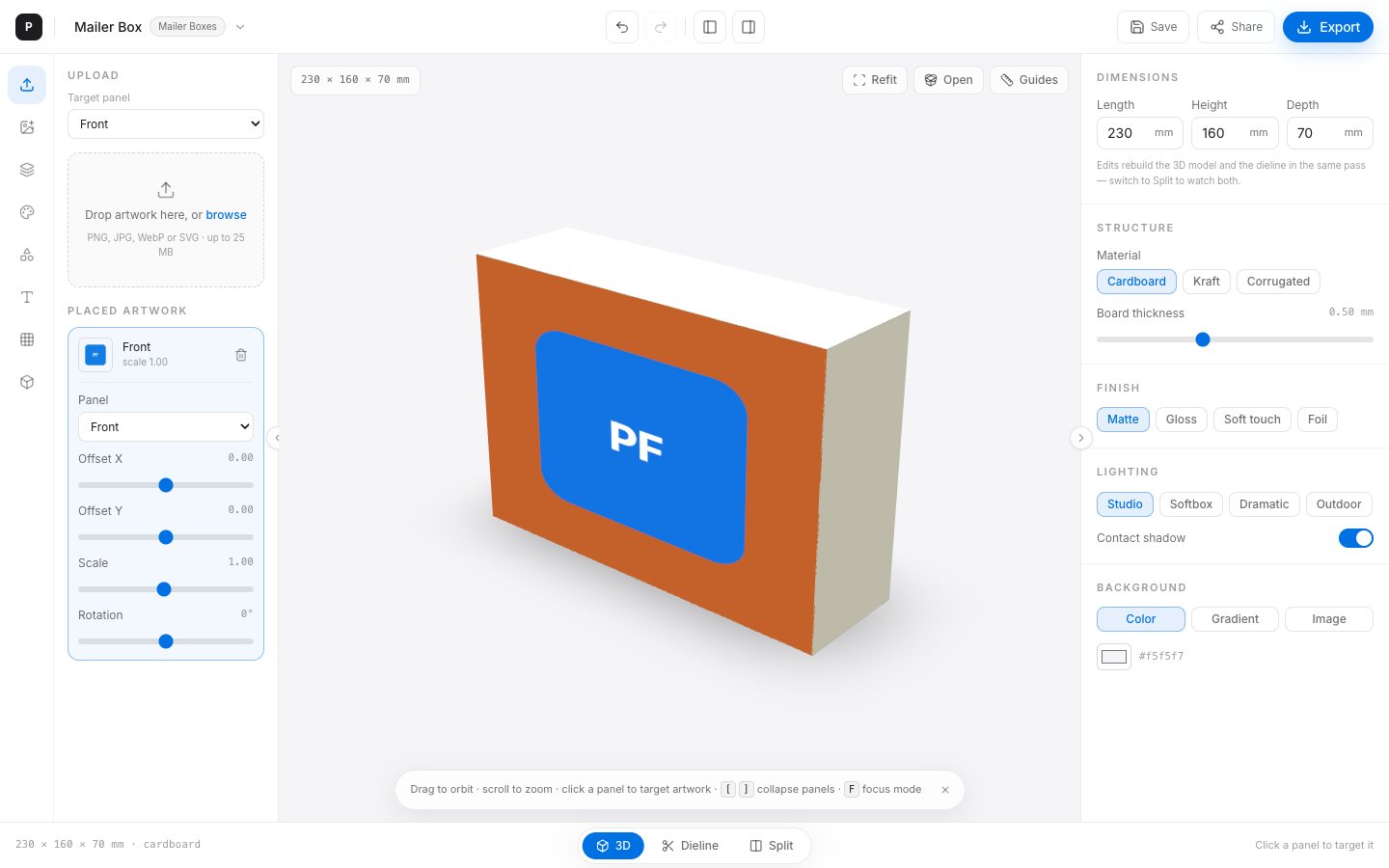
Artworks placed in the asset panel are drawn into dieline panel regions using SVG clip paths derived from each PanelRegion polygon. The same composite (package color + artwork) used in 3D feeds the 2D overlay — so transparent PNGs still show panel color on the blank.
6. Export SVG / DXF / PDF sheet
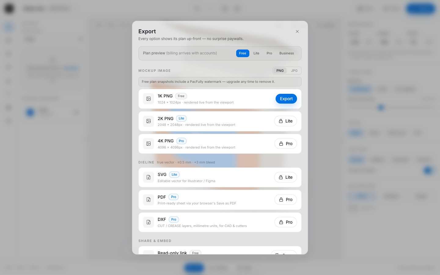
Open Export:
- SVG — themed vector download (Lite gate in UI)
- DXF — CAD-friendly R12 with CUT/CREASE/BLEED/DIMS (Pro gate in UI)
- PDF — opens a print-themed sheet → browser “Save as PDF” (Pro gate; not a true vector PDF writer yet)

7. Print considerations & bleed
- Default bleed guide is 3 mm (
DIELINE_BLEED_MM). - Documented manufacturing-plausible tolerance intent: ±0.5 mm — still proof with your converter.
- Safe-zone guides in 3D are separate overlays; do not confuse them with dieline bleed.
- Prefer SVG/DXF for prepress handoff; treat the PDF print sheet as a review artifact until a vector PDF writer ships.
8. Designing in Split view
Split is the recommended review mode for structural + graphic checks: orbit the mockup while confirming flap geometry and art placement on the blank. Panel highlight is shared — click either side to retarget artwork.
9. Limitations (honest)
- ScopeOnly 6 foldable structures — containers have no dieline by design.
- PartialNot die-cutter-certified; proof on press / with your converter.
- PartialPDF export = browser print stylesheet, not pdf-lib vector output.
- PreviewExport plan gates are client-preview until billing exists.
- APINo public
/v1/dielinesendpoint yet — generation is client-side.
Next
Return to the Editor guide for materials, GLB import, and shortcuts — or see Architecture for how generators sit in the monorepo.